
Hidden Errors in Autodesk Inventor: Why 3D Models Become Unstable
Autodesk Inventor tolerates many design inaccuracies. It rarely blocks operations and can produce geometry that looks correct even when underlying problems exist…
Contents
Autodesk Inventor is highly tolerant of design inaccuracies. It rarely blocks operations and can produce visually correct geometry even when questionable methods are used. This is why many technical failures are perceived as software errors, even though their root causes are introduced when the first sketch is created.
The most dangerous misconception in design is: "If the model regenerates without errors, it must be designed correctly." In practice, this is not always true.
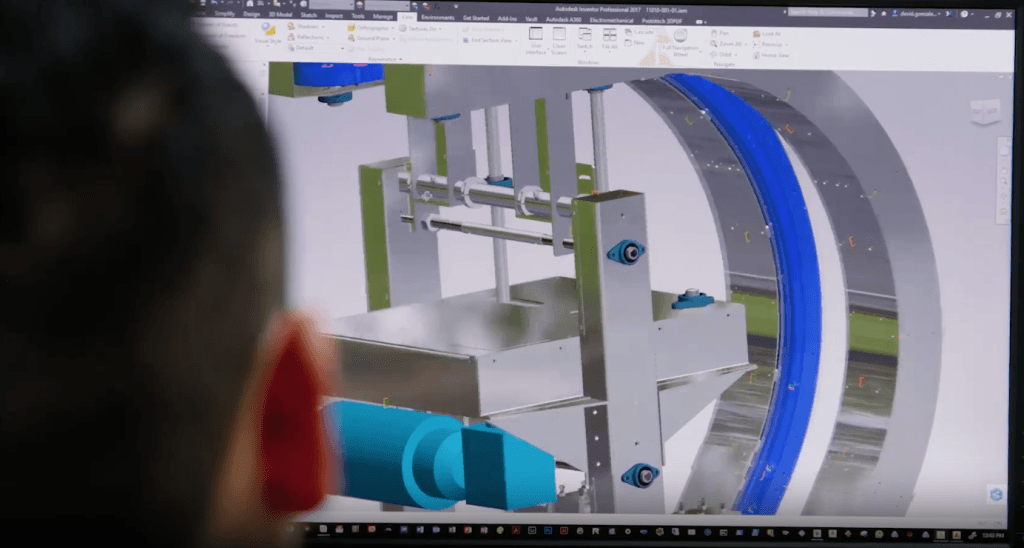
The Illusion of Stability: What the Feature Tree Hides
A model can open, export, and move to manufacturing successfully for a long time while remaining structurally unstable. Inventor allows problematic relationships: references to incidental geometry, dependencies on derived edges, overloaded sketches, or features that do not reflect the part's design logic.
The program does not distinguish temporary solutions from fundamental design architecture errors. It simply records the sequence of actions.
Practical Cases: Common Design Mistakes
Case #1: Dependencies on Derived Edges
- Incorrect approach: Referencing sketch geometry or constraints to edges created by fillet or chamfer operations.
- Risks: When a fillet radius changes or a chamfer is removed, the original edge disappears. This breaks references, creates feature tree errors, and damages downstream geometry.
- Recommended solution: Use origin planes and coordinate axes for references. Origin geometry remains unchanged regardless of subsequent part modifications.
Case #2: Overloaded Sketches Instead of a Modular Approach
- Incorrect approach: Creating one complex sketch containing the entire product profile with every hole and cutout.
- Risks: Changing a single parameter in such a sketch often causes overlapping lines and unpredictable geometry distortion. It also significantly increases calculation time during model regeneration.
- Recommended solution: Divide modeling into logical stages. Build the base geometry first, add major features next, and finish with minor details. A strict rule: one sketch should solve one design task.
Signs of a Structurally Unstable Model
The software does not audit the robustness of design decisions, but an unstable model shows characteristic signs:
- Difficulty making changes: Situations where rebuilding a part from scratch is easier than modifying it.
- Reduced performance
- An assembly freezes on opening despite having relatively few components. This can indicate cyclic dependencies or excessive sketches.
- Unpredictable behavior
- A change in one feature causes illogical regeneration of the entire part because of a tangled feature history.
- Excessive duplication
- Creating patterns and mirror features based on already mirrored geometry makes the original geometry harder to identify.
The Designer's Golden Rule
A high-quality model is not one that merely works today. It remains predictable when changes are made at any point in its life cycle.
A useful design principle is that another specialist should be able to understand the model without additional explanations. Parameter naming and the sequence of features in the feature tree should be completely transparent.
Checklist: How to Check Model Stability
Before submitting a project for work or saving the final version, it is recommended to review model stability against several key criteria. First, make sure sketches in the feature tree are fully constrained: they should have all necessary constraints and dimensions, indicated visually by a change in line color or a special icon.
It is important to minimize adaptivity in the final assembly, fully constrain dimensions, and reserve flexible relationships for the conceptual design stage. Clear naming conventions should also be followed, with meaningful names for key parameters such as length and diameter instead of default system identifiers.
The feature tree should contain no warnings about lost references or invalid geometry, because even if the part appears to regenerate successfully, such conflicts can substantially slow calculations. Finally, check that features follow a strict hierarchy: cosmetic operations such as fillets and chamfers should appear at the very end of the feature history and should not interfere with formation of the base topology.
Conclusion
Errors in Autodesk Inventor modeling methodology rarely appear immediately. They accumulate in the file structure and typically cause geometry failures when critical changes are made under time pressure. A systematic approach and strict modular modeling rules help avoid these risks.
If you are considering Autodesk Inventor for your workflows, you can get a 30-day trial. This will let you test the tool's features and evaluate model stability before purchasing.
Tel.: 8 (7172) 57-70-75, 57-80-28
- Mobile
- 8 (701) 550-18-93 (+Whatsapp)
- office@cad.kz